Air Constriction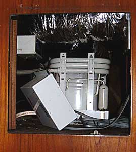
|
This compressor will be removed freeing up closet space and making the room quieter. The new compressor will be located in the engine room and only the air handler will be in the stateroom. The air handler will be mounted under the bunk and have isolators for sound reduction. This location will allow venting into the valance area. This room's air flow will no longer control the guest stateroom's air. |
| We had intended to mount the air handler under the berth but that endeavor was proving quite difficult. Since the new handler is much smaller and quieter we decided to mount it as far back in the original cabinet as possible. This will still allow enough room for a guest to store a duffle bag in the cabinet. |
Change of Plans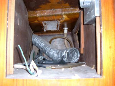
|
Running the Duct Work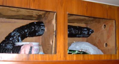
|
This photograph shows the port side cabinets. A 6" duct will run into the first cabinet and be split into a 4" duct that will dump into the port valance and a 3" (shown) that will dump into the starboad valance. |
| This photograph shows 3" duct running around front cabinets and into forward starboard cabinet to be dumped into the valance. |
Starboard Front Legs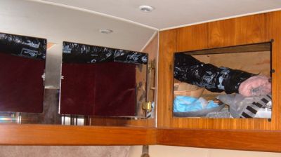
|
Tubing
|
This photograph shows the 1/4" and insulated 3/8" tubing, making the long run from the VIP Stateroom to the Engine Room. |
| The air handler will be installed in this closet located in the VIP Stateroom. The 3" insulated duct is routed to the Guest Head. The 3/8" and 1/4" copper tube will be routed back to the Engine Room and to the compressor. The 3/8" tubing is insulated. |
Getting Ready for Paint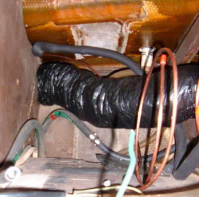
|
Air Troughs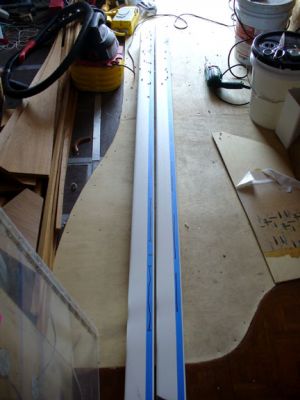
|
These 3x3 PVC fence posts will be mounted in the valance area of the VIP Stateroom and used as troughs for the flow of air. Marks were created for slots to be cut in the top side for the airholes. A larger hole (4" for port and 3" for starboard) has already been cut in the side for the flexable duct work. Slots farthest from the duct entry are cut smallest with increasingly larger slots cut closer, since most of the forced air will be at the end of the trough. |
| The portside air trough has been mounted. The 4" air duct enters through the cabinet on the left aft side. Small slots are at the far end. She is now ready for a valance to be mounted. |
Portside Air Trough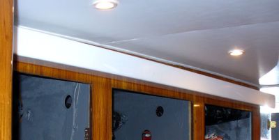
|
Starboard Trough
|
The starboard trough is mounted with a 3" flexible duct coming into the right side at the forward edge (left on photo). Smal air slots are on the aft (right side of photo) end of the trough. She is now ready for the valance to be mounted. |
| The air handler was mounted on a board coated with silent running and then fastened in place. Air duct and copper tubing are now all connected. The Dometic Cruisair SMX Series Control box is mounted on the upper left and the remaining electrical box is ready to be mounted. |
Air Handler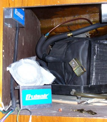
|
