Filling the Void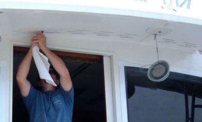
|
This is a very important project to me. I have seen many people try to solve this problem with little success. The station wagon effect brings diesel fumes and mist into the cockpit and bridge. Often times people think they are sea-sick, but the nausea is caused by this problem. In addition, the boat will be cleaner with less salt on the aft enclosure or salon window. My objective is to put air in the void that causes the vacum. Here we have cut 21 vent slots in the overhang to be fed by Munters' vents mounted on the bridge. A single long slot will be located at the steps. |
| The air from the Munters vents will be fed to the vents in the cockpit, through holes drilled in the starboard bridge side and under the sub floor. |
Air Holes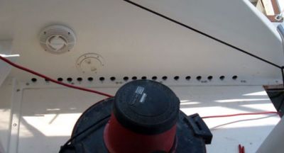
|
Air Flow
|
The air from the Munters vents will also be fed to the vents in the cockpit thru these holes drilled in the port side of the console and under the sub floor. |
| A total of eight of these slim vents will be mounted on the front of the bridge and will feed into the Munters vents. |
Slim Bridge Vents
|
Feeding the Munters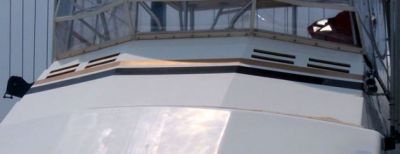
|
This photo shows the cut vent holes. There will be four on each side that feed into the Munters vents. The dry air will then flow around, through the floor, and into the vents in the cockpit. This should fill the void and eliminate the station-wagon effect. |
| The front of the bridge has three distinct sections: port, center, and starboad. This photo shows the starboard side. Four of the slim vents will be mounted into this side and fed into a box that will house the Munters vent. This configuration allows the Munters to be horizontal and for the slim vents to be seen on the outside of the bridge. The air will then flow into the bridge structure and route to our sub-floor leading to the cockpit vents. The same will be done for the port side. This should be plenty of air to acomplish what we intend. |
Munter Location
|
Bridge Munters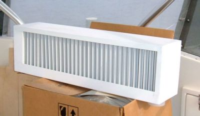
|
This is the back-side of one of the the Munters vents that will be used to cure the Station-Wagon effect. Note the large drain on its lower right side. This vent is for the starboard side. Water will be drained out of this outlet, through a hose and out the side of the bridge. Munters is important in this application for many reasons. We wanted to prevent water flow through and into the overhead of the cockpit and salt into the console area. |
| This is the front side of the Munters vent marked for the starboard side. Air flows through and out the back with little resistance, yet water and salt do not come through. |
Front of Munters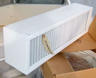
|
Spacers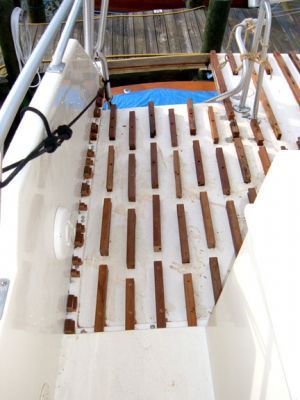
|
These spacers will allow air flow to the vents. A fiberglass floor will be installed on top of these spacers. |
| This photo shows more of the spacers. These are about 3" apart, across the bridge. |
More Spacers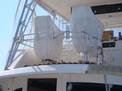
|
Air Channels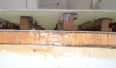
|
This photo shows the channels with the new floor on top. |
| We made the sheets of fiberglass for the floor at the barn and cut it to pattern. We then laid the PC on top of the spacers, and epoxied them, and laying everything we could on top of it to hold it in place. |
New Floor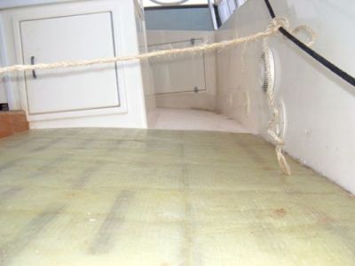
|
Two in Place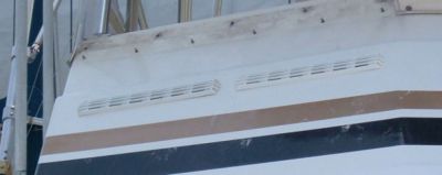
|
Here are two of the vents cut and in place. There will be four installed on the port side and the same on starboard. |
| Boxes were made to hold the Munters and have now been glassed/painted. They are now ready for installation. The box compensates for the angle at the front of the bridge and allows the placement of the Munters to be level. |
Boxed Munters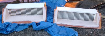
|
Munters Drain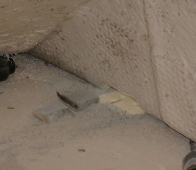
|
The first step in making the drain for the Munters' vent was cutting this hole in the bridge. It is located under the brow on the starboard side near the front of the bridge. A box will be made for the hose from the vent to run to and then flow out of this opening. |
| 3" PVC 45* pipe was glassed in. This will be used in the drain for the Munters Vent. A reducer will be used to put on a 1 1/2" hose to the vent. |
Drain Pipe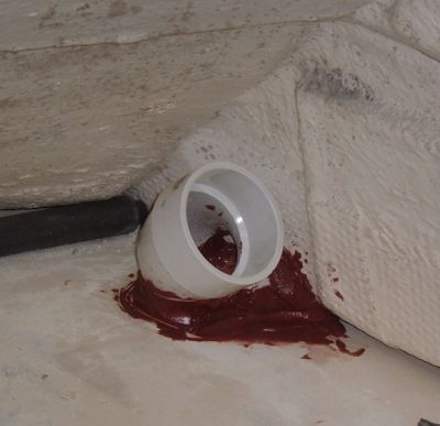
|
Outside Drain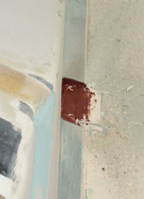
|
This is the outside of the vent drain. Wes will smooth it out and then glass a top over it to make it match the aft drains that were on the boats bridge. |
| To make it fit properly, this one took me 4 times as many cuts because I had to crawl to get to it. |
Small Space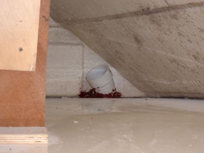
|
Munter's Mounted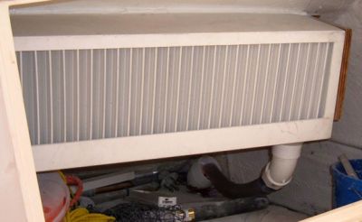
|
Munter's vents mounted in place. |
| The drain still needs to be finished but it will work while the boat is outside for a few days. |
Draining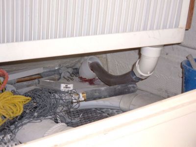
|
Test Area!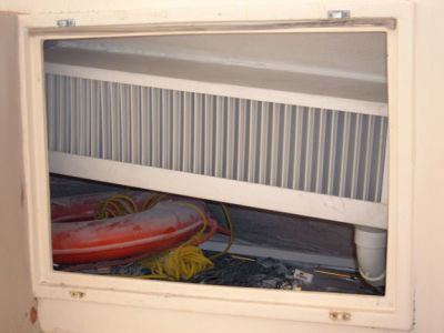
|
The location of this starboard vent will allow us to clearly see how well the Munter's vents really work. We can spray water directly into the vent and be able to see what comes through. |
| You can see the Munters' vents through these cutouts. Plastic louvers will be painted to finish off the cutouts. The Munters will let in air while keeping out salt and water. That air will flow under the bridge floor and into the cockpit in an effort to minimize the Station Wagon Effect found on most boats. |
Munters View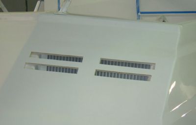
|
Louvers In Place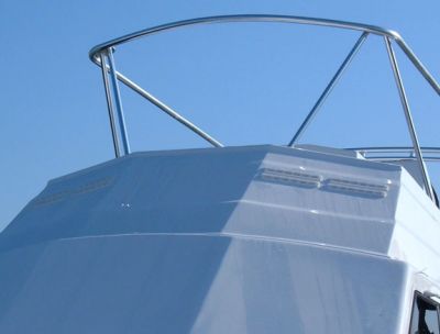
|
These louvers will scoop into the Munters while looking good. |
| Another view of the louvers. She looks pretty intimidating from this angle. |
Coming Atchya!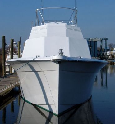
|


